For this question, our solution can become apparent with the calculation of 2 factors. For the sake of time management, we can choose to calculate the Current {I_t} of the battery with the end and start value of the variable resistor VR, which are 0 and 5.
So, the two questions we can now ask ourselves are:
-
When VR=0, what is {I_t} ?
-
When VR= 5, what is {I_t} ?
We can relate these two values by the equation V=IR
We can even rearrange the formula, to make I the subject; {I=\frac{V}{R}}
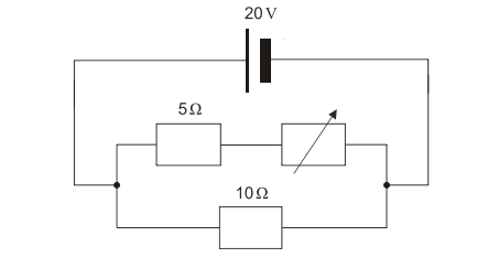
Since the circuit is a parallel circuit, we must note that {I_t} will inevitably split at the junction into the first branch of the circuit, where the 5 Ω. and variable resistor lay, and the second branch where the 10 Ω. resistor lays.
So we can call the current of the first branch {I_1} and the current of the second branch {I_2}.
With this is mind we also must note that after the current passes through these branches, it will rejoin again- which we can state with the formula:
{I_t}= {I_1}+ {I_2}
Now, we can begin the real calculations-
For when VR=0
Since the 5Ω resistor and the variable resistor are connected in series in the first branch, we use {R=R_1+R_2} for the final resistance of {I_1} .
For {I_1}; {R=R_1+R_2}= 5Ω+0Ω= 5Ω
{I_1=\frac{V}{R}}= {\frac{20V}{5Ω+0Ω}}= 4 A
{I_2=\frac{V}{R}}= {\frac{20V}{10Ω}}= 2 A
{I_t}= {I_1}+ {I_2}= 4A + 2A= 6A
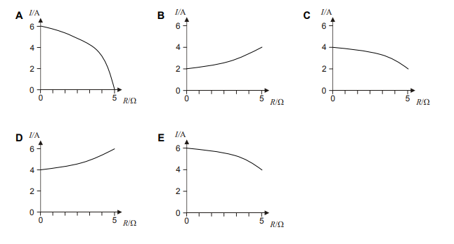
To put this into a position on the given graphs, we see that our X-axis is the Resistance in Ohms, and our Y-axis is the Current from the battery in Amperes.
(X,Y)= (0,6)
This alone eliminates options B, C and D- and we are left to analyze A or E.
Our final step is calculating For when VR=5
For {I_1}; {R=R_1+R_2}= 5Ω+5Ω= 10Ω
{I_1=\frac{V}{R}}= {\frac{20V}{10Ω}}= 2 A
{I_2=\frac{V}{R}}= {\frac{20V}{10Ω}}= 2 A
{I_t}= {I_1}+ {I_2}= 2A + 2A= 4A
Again, we put this into a position on the given graphs, where we know that our X-axis is the Resistance in Ohms, and our Y-axis is the Current from the battery in Amperes.
(X,Y)= (5,4)
Leaving our final answer to clearly be E.